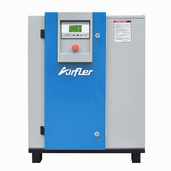
Operational Theory and Technical Breakdown
| Workflow | Four-Stage Cycle | |
| 1. Intake Phase | - Piston moves downward → Cylinder volume increases → Inlet valve opens → Ambient air is drawn into the cylinder due to pressure differential (< atmospheric pressure). | Inlet Valve Cylinder |
| (Intake Phase) | - Vacuum Level: Typically 0.8–0.95 bar (absolute pressure) (per ISO 1217 standards). | |
| 2. Compression Phase | - Piston moves upward → Air volume decreases → Temperature and pressure rise (following the ideal gas law ). | Compression Ratio Adiabatic Compression |
| (Compression Phase) | - Single-Stage Compression Ratio: 6:1–8:1 (ASME VIII pressure vessel design limit); multi-stage compression can exceed 20:1. | |
| 3. Discharge Phase | - Cylinder pressure exceeds system resistance → Outlet valve opens → High-pressure air flows into the receiver tank (target pressure range: 7–15 bar). | Outlet Valve Receiver Tank |
| (Discharge Phase) | - System Resistance: Includes pipeline pressure loss, receiver tank backpressure, and downstream equipment requirements. | |
| 4. Cooling Phase | - Compressed air is cooled via air-cooled fins (temperature drop: 30–50°C) or water-cooled jackets (higher efficiency). | Air-Cooled / Water-Cooled Heat Exchanger |
| (Cooling Phase) | - Necessity: Prevents lubricant carbonization, seal aging, and energy loss (high temperatures reduce volumetric efficiency). |
 English
 简体中文
简体中文 French
 English
 Portuguese
 Russian
 Spanish
