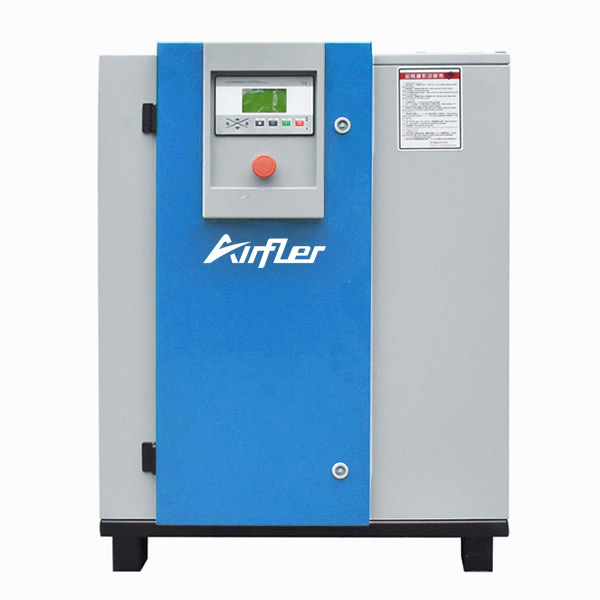
The working principle diagram of an air compressor typically includes the following core components and processes. Below is a text-based schematic breakdown (visual diagrams can be retrieved by searching keywords like "air compressor working principle diagram"):
Key Components (Piston-Type Compressor Example):
Inlet Valve
Air enters the compression cylinder through the inlet valve as the piston moves downward, creating a vacuum that draws in external air.
Compression Cylinder
The piston moves upward, reducing the air volume and increasing temperature and pressure (following the Ideal Gas Law, PV=nRT).
Note: Multi-stage compressors may include multiple cylinders to progressively increase pressure.
Outlet Valve
High-pressure air is discharged through the outlet valve into a receiver tank or downstream equipment.
Power Source (Drive System)
An electric motor or diesel engine drives a crankshaft, converting rotational motion into the piston’s reciprocating movement.
Cooling System
Heat generated during compression is dissipated via cooling fins (air-cooled) or coolant (water-cooled) to prevent overheating.
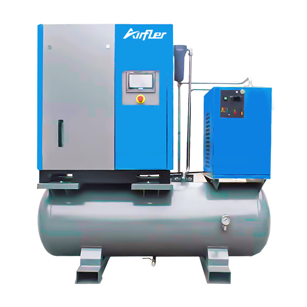
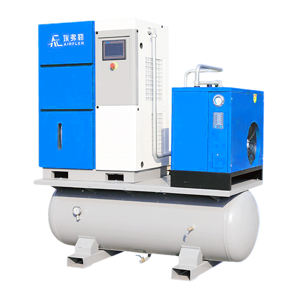
Receiver Tank & Pressure Switch
The tank stores compressed air, while the pressure switch controls the compressor’s on/off cycles to maintain target pressure.
 English
 简体中文
简体中文 French
 English
 Portuguese
 Russian
 Spanish
